شعار
وطن

غرفة اختبار درجة الحرارة والرطوبة

غرفة اختبار درجة الحرارة والرطوبة

  • Lab Companion Rapid Thermal Cycling Chamber for RF Devices: Detect Frequency Drift to Secure Design Validation Lab Companion Rapid Thermal Cycling Chamber for RF Devices: Detect Frequency Drift to Secure Design Validation
    Nov 19, 2026
    RF devices differ from ordinary electronic components in a key aspect: their core performance is defined by electrical parameters such as frequency, insertion loss and impedance, all of which are highly temperature-sensitive. A filter that meets specifications at room temperature may see its center frequency drift out of the passband at high temperatures; a power amplifier may suffer gain degradation at low temperatures, resulting in reduced signal coverage. For RF devices, rapid thermal cycling testing is not merely a reliability test to check whether components fail. It is a core verification method to evaluate RF performance stability across the full temperature range. Uniform and stable temperature conditions directly determine the credibility of RF measurement results. Rooted in Dongguan, Lab Companion has specialized in environmental reliability test equipment for over 20 years. Our self-developed rapid thermal cycling chamber for RF devices delivers precise temperature control and superior temperature uniformity, supporting performance validation for RF components. This article covers failure mechanisms, test impacts, equipment solutions and selection guidelines. 1. Mechanisms of Failure and Performance Degradation Under Temperature Variation 1.1 Frequency Drift The center frequency of a device is determined by the geometric dimensions of its resonant structure and the dielectric constant of the material. Temperature changes trigger thermal expansion and contraction of materials, alongside variations in dielectric constant. The combined effect leads to frequency offset. For filters, frequency drift shifts the passband and interferes with adjacent channels; for oscillators, it directly impairs output frequency accuracy. Most frequency drift is reversible, and parameters can recover once temperature returns to ambient. Nevertheless, it reveals risks of insufficient design margin. If the drift approaches the channel spacing limit, the RF link may lose lock under extreme temperatures. Therefore, swept parameter testing must be carried out at multiple temperature points across the full operating range, rather than only at room temperature. 1.2 Degradation of Insertion Loss and VSWR Conductor loss and dielectric loss change with temperature. Rising temperature increases conductor resistance and loss; low temperatures alter the dielectric properties of certain materials and degrade transmission performance. Meanwhile, thermal deformation causes impedance mismatch, shown as worsened return loss and higher VSWR. Fluctuating insertion loss reduces system power budget and receiver sensitivity. In cascaded multi-component systems, loss errors accumulate step by step. It is critical that the temperature characteristics of individual devices are repeatable and predictable. 1.3 Fatigue Degradation of Solder Joints and Interconnections RF circuits widely adopt microstrip lines, striplines and high-density vias with tiny solder joints. Repeated thermo-mechanical stress during thermal cycling easily induces fatigue cracks. Unlike conventional circuits, RF solder joints carry signal transmission. Poor contact directly raises loss and degrades VSWR, instead of only increasing DC resistance. Most RF modules adopt cavity packaging and connector interconnection. Mismatched CTE (coefficient of thermal expansion) between cavities and substrates, as well as variable connector gaps, are common weak points during thermal cycling. 1.4 Temperature Dependence of Substrate Material Properties The dielectric constant and loss tangent of high-frequency laminates are not fixed values. They vary with temperature, changing the electrical length and characteristic impedance of transmission lines and causing phase shift and matching failure. This effect is especially critical for phased-array radars and RF arrays that require strict phase consistency. 2. Impacts of Temperature Stability on In-Situ RF Testing 2.1 Non-uniform Temperature Field Introduces Irreparable Measurement Deviation RF testing demands stricter thermal conditions than general electrical testing. Large temperature gradients inside the chamber mean the DUT, calibration standards and test fixtures sit at different temperatures, introducing extra measurement noise to loss and VSWR readings. Such errors cannot be eliminated via post-processing and must be controlled at the testing source. When selecting equipment, do not rely solely on nominal temperature accuracy. Prioritize multi-point temperature uniformity under full load and long-term temporal stability. 2.2 Temperature Fluctuation Makes Scanned Data Unattributable RF parameter acquisition usually requires continuous sweeping. If chamber temperature fluctuates during measurement, data collected in different segments correspond to different thermal conditions, rendering the parameter curves invalid. Stable temperature plateaus are prerequisites for reliable RF thermal profiles. 2.3 Dedicated RF Feedthrough Ports Are Mandatory for In-Situ Testing Real-time monitoring of RF metrics during thermal cycling requires feeding signals into and out of the chamber. The chamber must be equipped with dedicated RF feedthrough ports, which must not compromise sealing or internal temperature uniformity. This detail is often overlooked yet essential for viable in-situ RF thermal cycling tests. 3. Lab Companion Rapid Thermal Cycling Chamber Solution for RF Devices 3.1 Wide Temperature Range to Validate Diverse RF Components Standard models cover -70℃ to +150℃, fully covering conventional high-low temperature ranges for RF qualification and leaving margin for accelerated testing. Passive and active components including filters, power amplifiers, RF switches and circulators can all be qualified in one chamber. 3.2 Precise Temperature Control and Uniform Thermal Field for Repeatable Data Temperature fluctuation ≤ ±0.3℃; temperature deviation ≤ ±2℃. Optimized air duct and circulating airflow design deliver excellent temperature uniformity. Stable thermal conditions ensure repeatable RF curves and comparable results among samples placed at different positions. 3.3 Multiple Linear Ramp Rates to Avoid Thermal Overshoot Adjustable linear ramp rates of 5℃/min, 10℃/min and 15℃/min suppress temperature overshoot and prevent unintended thermal stress on RF structures and solder joints. Ramp rates can be switched according to test profiles to balance throughput and test consistency. 3.4 Traceable Data + Customizable RF Ports for In-Situ Measurement The chamber automatically logs temperature profiles and test data for full traceability. Custom RF feedthrough ports and external interfaces are available to connect with vector network analyzers and other RF instruments for synchronous parameter capture during thermal cycling. Customization of chamber volume, ramp rate, temperature range, communication protocols and RF interfaces is supported to fit various RF modules and test schemes. 4. Selection Guidelines for RF Rapid Thermal Cycling Chambers 4.1 Verify Thermal Load Capacity Based on Device Power Dissipation Power amplifiers generate substantial heat during operation, especially under high-power test conditions. Confirm that the cooling capacity and airflow can offset heat dissipation to avoid temperature runaway under loaded conditions. Sizing based only on passive components will fail active amplifier testing later. 4.2 Validate Temperature Uniformity with Full-Load Actual Measurement Good performance at no load does not guarantee reliable full-load operation. Since RF parameters are extremely temperature-sensitive, request full-load multi-point temperature mapping data from the manufacturer. Where possible, run comparison tests with actual samples to confirm acceptable deviation across different mounting positions. 4.3 Plan RF Feedthrough Layout in Advance If in-situ RF measurement during thermal cycling is required, define port configuration and sealing solutions at the selection stage. Retrofit after equipment arrival often incurs high modification costs and delays projects. 4.4 Prioritize Long-Term Reliability and Local Support RF qualification often runs continuously for long durations. Equipment stability directly impacts project schedules. Lab Companion operates three R&D and manufacturing bases in Dongguan, Kunshan and Chongqing, with over 6,000 ㎡ production space and an annual output of approximately 2,000 environmental test chambers. Our nationwide service network supports long-term reliable operation. Conclusion The reliability of RF devices is reflected in curves of frequency drift, insertion loss and VSWR versus temperature. Frequency offset, loss variation, solder joint fatigue and high-frequency dielectric drift all emerge under rapid thermal cycling. Lab Companion rapid thermal cycling chambers for RF devices combine wide temperature range, precise control and uniform thermal fields, helping RF enterprises obtain authentic and trustworthy temperature characteristic data. Going forward, Lab Companion will continue to deepen its expertise in environmental reliability testing, delivering stable test equipment to support R&D validation for RF and microwave products.
    إقرأ المزيد
  • Lab Companion Rapid Temperature Change Test Chamber Manufacturer: Solid Technical Heritage, Reliable Production Capacity & Dependable Service Lab Companion Rapid Temperature Change Test Chamber Manufacturer: Solid Technical Heritage, Reliable Production Capacity & Dependable Service
    Nov 18, 2026
    Choosing a manufacturer is essentially choosing capability and assurance. Rapid temperature change test chambers are high-investment reliability test equipment. Procurement decisions shape your product validation capabilities for years to come. On the surface, buyers compare specifications and prices; at the core, they evaluate technical expertise, manufacturing capacity, service support and qualification credentials. As an environmental reliability test equipment manufacturer based in Dongguan, Guangdong, China, with over 20 years of industry experience, Lab Companion delivers trustworthy solutions across four pillars: technology, production capacity, service and qualifications. This article outlines a practical evaluation framework to help global purchasers select the right supplier. 1. Technical Capability: True Expertise in Temperature Cycling 1.1 Temperature Ramp Rate & Linear Control The biggest technical challenge for rapid temperature change lies in ramp rate and linearity. Many suppliers only advertise ramp rates without specifying linear performance, leading to large deviations between actual temperature profiles and set parameters. To assess a manufacturer’s technical strength, focus on their linear temperature control and overshoot suppression solutions. 1.2 Wide Temperature Range & Temperature Uniformity Combining a wide temperature range with fast temperature cycling places heavy demands on refrigeration systems and air duct design. Critical benchmarks include proven experience in wide-range projects and availability of full-load temperature uniformity test reports. 1.3 Control Accuracy & Long-Term Stability Temperature fluctuation and deviation metrics should not be judged only by nameplate values. Long-term continuous running stability matters most. Manufacturers with mature self-developed control algorithms and complete internal validation systems can maintain consistent accuracy over years of operation. 2. Manufacturing & Capacity: Stable Delivery & Customization 2.1 Scaled Production & Predictable Lead Times Environmental test equipment is highly customised. Lead times directly affect your project schedules. A well-established scaled manufacturing system ensures stable production, on-time delivery and consistent quality across batches. 2.2 Custom Engineering for Unique Test Requirements Industries vary widely in temperature profiles, chamber volume, temperature zones, communication interfaces and data acquisition needs. Strong customisation capability enables the equipment to fit your actual test workflow, instead of forcing your test plan to adapt to standard off-the-shelf models. 2.3 Quality Management & Pre-Shipment Validation Rigorous factory acceptance testing is the foundation of quality. Full performance verification before shipment reduces on-site commissioning risks and shortens your equipment commissioning cycle. 3. Service & Qualifications: Long-Term Partnership Support 3.1 Installation, Commissioning & Operator Training Professional installation, commissioning and hands-on training are critical at the start-up phase. Localised technical teams help you quickly establish standard reliability test procedures. 3.2 Fast After-Sales Support & Spare Parts Supply Continuous operation inevitably requires maintenance. Response speed and spare parts stock directly minimise downtime. A nationwide service network across China cuts waiting time for repairs and technical support. 3.3 Official Qualifications as Independent Proof of Strength National High-Tech Enterprise and Specialized, Refined, Differential & Innovative Enterprise (SRDI) certifications are objective evidence of robust R&D capabilities and standardized management. These credentials serve as reliable references during supplier evaluation. 4. Lab Companion: Strength Delivered Across Four Pillars 4.1 Technology: Over 20 Years of Expertise in Environmental Test Equipment Rooted in Dongguan, Guangdong, China, Lab Companion has specialised in environmental reliability test equipment for more than two decades. Our standard rapid temperature change test chambers cover -70℃ to +150℃, with optional ramp rates of 5℃/min, 10℃/min and 15℃/min. Temperature fluctuation: ±0.3℃; temperature deviation: ±2℃. We continuously optimise linear temperature cycling and temperature overshoot control. 4.2 Production Capacity: Three Manufacturing Bases in China to Secure Delivery We operate three R&D and manufacturing facilities in Dongguan, Kunshan and Chongqing, China, with a total production area exceeding 6,000 ㎡. Our annual output reaches approximately 2,000 units of environmental test equipment. We support customisation on chamber volume, ramp rate, temperature range, communication protocols and data acquisition systems. 4.3 Service: Nationwide Service Network, Ready for Smart Factory Integration The chambers automatically record temperature curves and raw test data. Optional industrial communication interfaces including MES, EAP and SECS-GEM allow seamless integration with automated production lines. Supported by our service network across China, we provide full-lifecycle technical support. 4.4 Qualifications: Certified High-Tech & SRDI Enterprise Founded in 2005, with a registered capital of RMB 10 million, our headquarters is located in Dongguan, Guangdong, China. We hold official National High-Tech Enterprise and Guangdong SRDI Enterprise certifications, backed by verified R&D and management systems. Conclusion Selecting a rapid temperature change test chamber supplier is an investment in your long-term reliability validation capability. Lab Companion from China stands out with solid technical accumulation, stable large-scale production capacity, comprehensive nationwide service network and authoritative qualifications. When you choose test equipment, you choose a long-term partner. We aim to help every enterprise find a reliable supplier that truly understands temperature cycling, prioritises quality and delivers sustainable technical support.
    إقرأ المزيد
  • LabCompanion Rapid Thermal Cycling Test Chamber: Stable Temperature Control for Long-Duration Thermal Stress Accumulation Testing
    Nov 17, 2026
    In the field of environmental reliability validation, rapid thermal cycling chambers are widely adopted yet often oversimplified test equipment. They are also known as thermal cycling chambers or TC chambers across the industry. While named differently, they serve the same core purpose: to expose test samples to controlled cyclic temperature changes and pre-emptively uncover latent weaknesses in product design, materials and processes. These naming variations stem from internal practices and industry conventions. The true value of a chamber lies in its ability to apply the predefined temperature profile to DUTs stably and reproducibly. Rooted in Dongguan, LabCompanion has specialized in environmental reliability test equipment for over two decades. Our rapid thermal cycling chambers deliver robust performance across three core metrics: thermal ramp rate, temperature range and temperature uniformity. This article starts with the fundamentals of thermal cycling testing and builds a practical evaluation framework for equipment selection. 1. What Does Rapid Thermal Cycling Testing Actually Evaluate? 1.1 Thermal Ramp Rate: Intensity of Thermal Stress Loading Thermal ramp rate is the most intuitive specification of a rapid thermal cycling chamber. A faster ramp rate creates a larger temperature shift per unit time. Mismatched coefficients of thermal expansion (CTE) between dissimilar materials concentrate thermo-mechanical stress, especially at stress-sensitive locations such as solder joints, packaging layers and adhesive interfaces. This accelerates the onset of fatigue cracks, delamination and other failures to shorten validation cycles. Still, a higher ramp rate is not always better. Industry standards specify clear ramp rate windows. Testing outside these limits alters failure mechanisms and renders results non-comparable. The proper validation workflow is to define the target ramp rate based on applicable standards or field operating conditions first, then verify whether the chamber can sustain stable performance within that range. 1.2 Temperature Range: Compatibility with Multiple Test Profiles Temperature coverage dictates the scope of test scenarios a chamber can handle. Automotive electronics commonly require -40℃ to +125℃; optical communication devices typically use -40℃ to +85℃, while some special components demand even lower temperatures. Insufficient temperature coverage forces manufacturers to deploy multiple separate chambers, raising capital investment and operational overhead. The real benchmark for a wide temperature range is not merely reaching the setpoints, but maintaining precise control at both extremes. Cooling loads surge and efficiency drops at low temperatures, while local overheating risks emerge at high temperatures. Reliable wide-range performance means consistent accuracy across the full span. 1.3 Temperature Uniformity: Ensuring Fair and Valid Test Results Significant temperature deviations across different positions inside the chamber create unequal stress conditions for samples in the same batch, invalidating test judgements. Many chambers show good performance under no-load conditions, yet uniformity degrades sharply once DUTs are loaded and airflow paths are blocked. For this reason, uniformity must be assessed based on loaded test data, not factory no-load nominal values. 2. Linear Ramp Control Is Critical for Credible Test Results 2.1 Nominal Ramp Rate ≠ Actual Temperature Profile A labelled rating such as 10℃/min represents an average rate under specific reference conditions. In real operation, temperature curves often slow down at the start and end of ramps while speeding up in the middle, or overshoot the target temperature. These deviations accumulate and change the total thermal stress experienced by samples. Reliability data loses rigor if judgements rely solely on nominal ramp rates instead of actual non-linear profiles. 2.2 Temperature Overshoot Introduces Unintended Extra Stress Temperature overshoot occurs when the temperature exceeds the setpoint before settling back. This extra fluctuation outside the defined profile adds unplanned stress. For thermally sensitive semiconductors and optoelectronic components, overshoot can trigger atypical failures and complicate root-cause analysis. Stable linear control and overshoot suppression are prerequisites for traceable failure analysis. 2.3 Full-Range Ramp Consistency Eliminates Test Distortion During wide-span thermal cycling, heating and cooling systems deliver uneven output across different temperature zones: cooling efficiency declines at low temperatures while heating has ample margin at high temperatures. Chambers without coordinated control suffer abrupt ramp-rate shifts. LabCompanion chambers adopt coordinated hot-cold regulation and segmented ramp compensation algorithms to deliver smooth, consistent profiles. When qualifying equipment, do not judge based on a single temperature segment. Request full temperature logs to check ramp stability, sudden shifts and overshoot. Actual logged curves carry more weight than datasheet specifications. 3. LabCompanion Rapid Thermal Cycling Chamber Solutions 3.1 Wide Temperature Range for Multi-Industry Standard Testing Standard models cover -70℃ to +150℃. A single chamber accommodates mainstream reliability temperature profiles for automotive electronics, optical communication, semiconductors and industrial electronics, with margin reserved for accelerated stress testing. It removes the need for redundant equipment investments. 3.2 Multiple Ramp Rates to Match Diverse Standards Supported ramp rates include 5℃/min, 10℃/min and 15℃/min, switchable on one unit to satisfy different test specifications. Thermal ramps remain linear throughout, with overshoot and segmental rate jumps well controlled. This guarantees comparable data across batches and test units. 3.3 Precision Control and Excellent Loaded Uniformity Temperature fluctuation: ≤ ±0.3℃; temperature deviation: ≤ ±2℃. Optimized ducting and circulating airflow preserve uniform temperature across all chamber zones under loaded conditions. All samples within one batch receive equivalent thermal stress for objective, consistent test evaluation. 3.4 Digital Data Traceability for Smart Factories The system automatically captures and archives full temperature profiles and test records for complete traceability. It supports industrial communication protocols including MES, EAP and SECS-GEM for automatic result upload, aligning with digital manufacturing workflows. Customization is available for chamber size, ramp speed, temperature range and communication interfaces. 4. Practical Equipment Selection Guidance 4.1 Define Test Profile Before Matching Equipment Capabilities Do not start procurement by comparing datasheets. First finalize your full test profile: temperature limits, ramp rate, cycle count and dwell duration. Match chamber specifications afterward with appropriate safety margin. Reversing this sequence often leads to equipment with impressive specs that fail to align with standards or field requirements. 4.2 Select Chamber Volume Based on DUT Size and Batch Quantity Volume selection balances two factors: maximum DUT dimensions determine usable inner space, while batch size dictates the number of fixture layers. Undersized chambers crowd samples and disrupt airflow. Oversized chambers increase energy consumption and extend cycle time, lowering throughput. Choose a chamber with moderate spare capacity based on your primary products. 4.3 Validate Against Real Curves, Not Just Published Specifications During vendor evaluation, request complete temperature profiles for your target test range. Focus on three criteria: ramp stability, overshoot magnitude and curve smoothness. Whenever feasible, run a loaded trial with your own samples to verify real performance, which outweighs marketing materials. 4.4 Prioritize Long-Term Stability and Lifecycle Support Rapid thermal cycling chambers run continuously at high frequency for years. Long-term operational stability matters more than factory-new performance. Assess manufacturers by their manufacturing infrastructure, internal validation system and service network. LabCompanion operates three R&D and manufacturing bases in Dongguan, Kunshan and Chongqing, with over 6,000 ㎡ production space and an annual output of around 2,000 environmental test chambers. Our nationwide service network supports reliable equipment operation throughout the full lifecycle. Conclusion The performance ceiling of your rapid thermal cycling chamber defines the upper limit of your reliability validation capacity. Ramp rate, temperature coverage and temperature uniformity work in tandem to determine whether test data is credible, repeatable and benchmarkable. LabCompanion rapid thermal cycling chambers combine wide temperature range, multi-ramp flexibility and high-precision linear control to support reliability validation for semiconductors, optical communication, automotive electronics and more. We keep advancing in environmental reliability testing to ensure every thermal cycling test produces defensible, auditable results.
    إقرأ المزيد
  • Lab Companion -40°C Temperature Cycling Chamber | Batch Testing for Automotive & Industrial Screening Lab Companion -40°C Temperature Cycling Chamber | Batch Testing for Automotive & Industrial Screening
    Nov 06, 2026
    -40°C is a widely adopted low-temperature limit for reliability temperature cycling tests. Automotive electronics, industrial control modules and outdoor communication products must withstand drastic temperature changes to verify their resistance to thermal stress across a wide temperature range. With over 20 years of expertise in environmental reliability test equipment, Lab Companion offers this -40°C temperature cycling chamber tailored to temperature cycling screening requirements under automotive and industrial standards. 1. Applicable Industries 1.1 Automotive Electronics Automotive components operate under alternating high and low temperatures. Cold start performance is a critical test item, and -40°C serves as the standard low-temperature limit for temperature cycling tests, validating component stability under thermal cycling. 1.2 Industrial Control Industrial control equipment is deployed in factories and open-air sites with broad operating temperature ranges. Temperature cycling tests covering -40°C assess the reliability of mainboards and drive modules in low-temperature conditions. 1.3 Outdoor & Communication Equipment Base stations and outdoor terminals are exposed to seasonal temperature swings. -40°C cycling simulates severe winter conditions to verify long-term durability for field deployment. 2. Key Performance Criteria 2.1 Low-Temperature Steady Cooling Capacity Reliably cooling from ambient down to -40°C and maintaining set temperature is fundamental for cycling tests. The refrigeration system ensures stable low-temperature hold to complete the full temperature profile. 2.2 High-Low Temperature Transition Performance Cycling requires repeated switching between -40°C and high-temperature setpoints. The chamber delivers smooth temperature transitions, faithfully following programmed profiles and avoiding excessive overshoot that compromises test validity. 2.3 Temperature Uniformity & Control Accuracy Consistent chamber conditions are essential when testing batches of samples. Superior temperature uniformity and precision guarantee identical test conditions for all specimens, enabling comparable and trustworthy results. 3. Lab Companion Chamber Advantages 3.1 Stable Cooling at -40°C Standard models cover a temperature range of -70°C ~ +150°C. Stable cooling and reliable temperature holding at -40°C fully meet low-temperature cycling requirements for mainstream automotive and industrial specifications. 3.2 Smooth Cycling with Minimized Temperature Overshoot Repeated transitions between -40°C and high temperatures follow a smooth, controllable profile with reduced overshoot to keep tests compliant with defined specifications. 3.3 Multiple Ramp Rates & Precise Control Selectable ramp rates: 5°C/min, 10°C/min, 15°C/min. Temperature fluctuation ≤ ±0.3°C, temperature deviation ≤ ±2°C. High control accuracy is maintained across both low and high temperature zones. 3.4 Batch Testing & Traceable Test Data Multi-layer sample racks are available for simultaneous cycling of multiple test pieces. Temperature profiles and logs are automatically saved to support quality control and full data traceability. 4. Selection Guidelines 4.1 Define Low-Temperature Limit Based on Test Standards Check your product specification first. If only -40°C testing is required, choose a matching model to optimize cost. Select a wider-range chamber if lower-temperature testing may be needed for future projects. 4.2 Prioritize Low-Temperature Steady-State Performance Do not rely solely on the labeled temperature range. Verify cooling stability and long-duration hold performance at -40°C under continuous cycling to ensure genuine and controllable test conditions. 4.3 Consider Long-Term Reliability & After-Sales Support Temperature screening often runs nonstop for extended periods. Select an established manufacturer with mature production and nationwide service networks to support reliable equipment operation throughout its lifecycle. Conclusion The -40°C temperature cycling chamber is essential reliability screening hardware for automotive electronics, industrial control and communication products. Drawing on decades of experience in environmental test equipment design and manufacturing, Lab Companion delivers chambers featuring stable low-temperature performance, smooth thermal cycling, flexible ramp rates and precise control. We provide robust temperature cycling solutions for automotive and industrial reliability validation. Lab Companion keeps innovating to deliver high-performance test equipment for reliability engineering worldwide.
    إقرأ المزيد
  • Lab Companion BMS Thermal Cycling Chamber: Board-Level Reliability Validation for Long-Term Stable BMS Operation Lab Companion BMS Thermal Cycling Chamber: Board-Level Reliability Validation for Long-Term Stable BMS Operation
    Nov 05, 2026
    The Battery Management System (BMS) serves as the core component of power battery and energy storage systems, responsible for cell condition monitoring, charge-discharge control and safety protection. Deployed long-term in energy storage power stations and new energy vehicles, BMS is exposed to drastic ambient temperature variations. The reliability of its board-level circuits and sensing components directly determines the safety and performance of the entire battery system. Thermal cycling test is a core reliability verification method for BMS, which applies alternating thermal stress to validate its service stability across a wide temperature range. With over 20 years of expertise in environmental reliability testing equipment, Lab Companion provides dedicated thermal cycling chamber solutions for the new energy industry. 1. Typical BMS Failure Mechanisms under Thermal Cycling 1.1 Thermal Fatigue of Solder Joints and Interconnections During repeated temperature swings, BMS board-level solder joints and interconnect structures are subjected to cyclic thermo-mechanical stress. Accumulated stress may trigger solder joint fatigue and contact resistance drift, resulting in abnormal acquisition and control signals. 1.2 Parameter Drift of Sensing Components Voltage, current and temperature sensing devices integrated in BMS are temperature-sensitive. Temperature fluctuations can cause parameter drift and degrade monitoring accuracy, bringing risks such as inaccurate SOC estimation and false protection triggers. 1.3 CTE Mismatch of Heterogeneous Materials A BMS PCB consists of diverse materials including substrates, IC chips, connectors and power devices. The mismatch in coefficient of thermal expansion (CTE) generates continuous internal stress under thermal cycling, which may gradually lead to board warpage, interface delamination and hidden interlayer damage. 2. Value of Thermal Cycling Validation for BMS 2.1 Verify Sensing Stability over Wide Temperature Range BMS must maintain measurement accuracy across its full operating temperature window. Thermal cycling tests verify the retention of acquisition accuracy after repeated temperature alternation, ensuring credible and continuous battery state monitoring. 2.2 Uncover Hidden Board-Level Process Defects Alternating thermal stress amplifies latent defects such as cold solder joints, poor connector contact and SMT process flaws. Early failure screening can be completed before product delivery to avoid field failures. 2.3 Underpin Battery System Safety and Quality Control BMS reliability forms the first safety barrier of battery systems. Thermal cycling data supports reliability assessment, design optimization and process control, and helps improve batch consistency of BMS products. 3. Core Advantages of Lab Companion BMS Thermal Cycling Chamber 3.1 Ultra-Wide Temperature Range Covering Full Application Scenarios Temperature range from -70℃ to +150℃, covering extreme working conditions of new energy vehicles, commercial & residential energy storage systems, complying with strict thermal cycling requirements of national standards, automakers and energy storage specifications. 3.2 Multiple Temperature Ramp Rates for Diverse Test Standards Available ramp rates of 5℃/min, 10℃/min and 15℃/min, flexibly adaptable to AEC-Q and internal enterprise specifications, balancing test rigor and laboratory throughput. 3.3 High Precision Temperature Control for Batch Testing Temperature fluctuation ≤ ±0.3℃, temperature deviation ≤ ±2℃. Customizable multi-layer sample racks support parallel testing of multiple BMS main control boards and sampling boards to boost verification efficiency. 3.4 Automatic Data Logging for Full Quality Traceability The chamber automatically records real-time temperature curves and test logs. Complete test records can be exported and archived to satisfy traceability, audit and certification requirements of the new energy sector. 4. Guidelines for BMS Thermal Cycling Chamber Selection 4.1 Match Chamber Volume with Sample Size and Test Batch BMS varies greatly in dimension, from small sampling boards to integrated main control units. Select chamber size and sample rack configuration according to sample dimensions, batch quantity and lab test cycle. 4.2 Plan Compatibility with BMS Test Platforms Most BMS thermal cycling tests require synchronous online signal acquisition under high/low temperature conditions. Confirm cable ports and signal interfaces during selection for seamless integration with external BMS test fixtures. 4.3 Prioritize Long-Run Stability and After-Sales Support BMS thermal cycling tests often run continuously for hundreds of hours. Choose well-established manufacturers with robust equipment stability and nationwide service networks to guarantee reliable operation and timely maintenance throughout the equipment lifecycle. Conclusion Identifying potential BMS failure risks at the board level via thermal cycling reliability validation is critical to secure long-term safe operation of battery systems. Lab Companion’s dedicated BMS thermal cycling chamber integrates wide temperature range, adjustable ramp rates, high-precision control, batch testing and traceable data logging, delivering reliable testing equipment for BMS R&D, validation and mass production screening. Going forward, Lab Companion will continue innovating environmental test technologies and provide higher-standard reliability testing solutions for the new energy industry.
    إقرأ المزيد
  • Lab Companion Compact Rapid Thermal Cycling Chamber Lab Companion Compact Rapid Thermal Cycling Chamber
    Nov 04, 2026
    Space-saving & Energy-efficient, Ideal for Laboratories and On-site Testing Value of Compact Rapid Thermal Cycling Chambers For R&D labs, low-volume pilot production and quality inspection, many companies do not require large-volume thermal cycling chambers. Instead, they prefer compact, flexible and user-friendly test equipment. Our compact rapid thermal cycling chamber delivers full thermal cycling reliability performance in a small footprint, perfectly catering to testing of small samples and low-batch runs. With over 20 years of expertise in environmental reliability test equipment, Lab Companion develops compact rapid thermal cycling chambers to serve R&D laboratories and low-volume production testing. 1. Application Scenarios 1.1 R&D Laboratory Validation Prototypes and small samples go through frequent iterations in the R&D phase and require repeated thermal cycling tests. This compact unit can be placed directly on lab benches for immediate testing, greatly accelerating R&D verification. 1.2 Stress Screening for Low-volume Pilot Runs Sample quantities are limited during new product pilot production. Large chambers run at low utilization and incur high energy costs. The compact rapid thermal cycling chamber handles stress screening for small batches independently, cutting capital investment and operational costs. 1.3 On-site & Off-line Inspection It can be deployed beside production lines or inspection stations for spot checks. Flexible placement eliminates the need to send samples to a central test room and speeds up quality response. 2. Key Specifications 2.1 Full Temperature Range & Ramp Rates, No Performance Compromise Small in size but equivalent to large chambers in core testing capability. The standard compact rapid thermal cycling chamber covers -70℃ to +150℃, with selectable ramp rates of 5℃/min, 10℃/min and 15℃/min to meet thermal cycling reliability requirements for electronic components and assemblies. 2.2 Stable & Precise Temperature Control Small cavities have low thermal mass and are prone to temperature fluctuations. Optimized control algorithms and air duct design deliver temperature fluctuation ≤ ±0.3℃ and temperature deviation ≤ ±2℃, maintaining consistent thermal conditions and repeatable test results. 2.3 Small Footprint & Low Power Consumption It occupies minimal floor space and draws less power, with lower requirements for lab layout and electrical supply — perfect for space-constrained R&D and inspection areas. 3. Lab Companion Solution Highlights Compact Design, Uncompromised Performance: Built in a space-saving layout with -70℃ ~ +150℃ working range and multiple ramp rate options, matching the reliability test capacity of larger chambers. Uniform Thermal Field for Trustable Data: Advanced temperature control offsets cavity disturbance common in small chambers and ensures stable, consistent test outcomes. Intuitive Operation & Traceable Records: Simple HMI for fast test program setup and recall. The system automatically logs temperature profiles and test data to support R&D archiving, quality traceability and audit compliance. 4. Selection Guidelines Select based on sample size and batch quantity: Evaluate chamber volume according to sample dimensions, loading capacity and available workspace. Compact models are recommended for R&D and spot inspection to avoid waste of space and power from over-sized equipment. Verify core performance parameters: Many compact chambers on the market reduce temperature range, ramp speed or temperature accuracy. Confirm working range, ramp rate, fluctuation and deviation to ensure compliance with your test standards. Consider long-term stability and service support: Compact test chambers also require reliable operation and routine maintenance. Choose an established manufacturer with mature production and nationwide service networks to secure full-lifecycle support. Conclusion Compact rapid thermal cycling chambers solve key pain points for R&D and low-volume quality testing through small footprint and flexible deployment, without sacrificing core reliability performance. Lab Companion specializes in environmental reliability test equipment. Our compact rapid thermal cycling chamber combines space efficiency, wide temperature range, multiple ramp rates, precise temperature control and easy operation to support efficient R&D validation and small-batch stress screening. Moving forward, Lab Companion will keep innovating to deliver more flexible and reliable thermal cycling test solutions for global industries.
    إقرأ المزيد
  • Lab Companion Rapid Thermal Cycle Chamber: Full-Lifecycle Reliability Testing for SSDs from R&D to Mass Production Lab Companion Rapid Thermal Cycle Chamber: Full-Lifecycle Reliability Testing for SSDs from R&D to Mass Production
    Oct 28, 2026
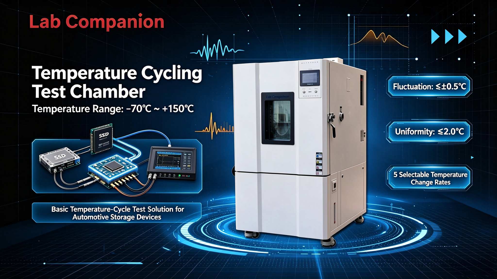
    1. Reliability Testing Requirements for Enterprise-Grade SSDs 1.1 Operating Temperature Range & Thermal Cycling Requirements Enterprise-grade solid-state drives (SSDs) are widely deployed in data centers and servers under high-load conditions. They must maintain consistent read/write performance across a wide temperature envelope. In accordance with JEDEC standards, industrial storage devices are qualified for an operating temperature range of -40°C to +85°C and a storage temperature range of -55°C to +125°C. Rapid thermal cycling between extreme high and low temperatures verifies the reliability of flash chip packages under abrupt temperature transitions. Visit https://www.lab-companion.com/ for more information. 1.2 Differentiated Requirements Across R&D to Mass Production SSD reliability validation is not limited to a single test phase. R&D phase: Wide temperature range and high-precision control to capture performance limits under extreme conditions Design validation phase: Repeatable and consistent test results for EVT/DVT qualification Pilot run phase: Scalable capacity for batch parallel testing Mass production phase: High throughput, automated operation and long-term stable runtime A unified thermal cycling platform covering the full product lifecycle reduces capital expenditure and significantly improves test efficiency. 2. SSD Failure Mechanisms under Thermal Stress 2.1 Performance Drift Induced by Thermal Cycling Temperature fluctuations alter the electrical characteristics of flash memory particles and controllers. Repeated cycling between -40°C and +85°C may cause drift in flash read/write performance and timing parameters, alongside shifts in controller power consumption and temperature-sensitive variables. Sustained thermal stress can lead to solder joint fatigue and package interface delamination, manifesting as intermittent read/write errors or inconsistent performance. 2.2 Data Retention and Batch Consistency Enterprise-grade SSDs have stringent data retention specifications. Thermal cycling accelerates charge leakage and degrades data retention performance. Batch consistency is critical during mass screening: uneven temperature stress across samples leads to ambiguous failure judgment, making chamber temperature uniformity a key performance metric. 3. Applicable Standards 3.1 JESD22-A104 Temperature Cycling Temperature cycling tests for enterprise-grade SSDs generally follow JEDEC JESD22-A104. Tests are performed between -40°C and +85°C with defined dwell times at temperature plateaus, simulating alternating cold and hot operating conditions. The standard specifies clear requirements for temperature ramp rate and cycle count. 3.2 ESS (Environmental Stress Screening) Methodology Environmental Stress Screening (ESS) is widely adopted in mass production. High-accelerated thermal cycling applies controlled stress to units under test to precipitate latent defects, exposing early failures before shipment. It balances validation rigor and production throughput. 4. Lab Companion Solution 4.1 Rapid Thermal Cycle Chamber for R&D & Validation The Lab Companion rapid thermal cycle chamber is designed for temperature cycling reliability testing of enterprise-grade SSDs. Key specifications: Temperature range: -70°C ~ +150°C, fully covering the -40°C ~ +85°C operating window and -55°C ~ +125°C storage window Temperature stability: ≤ ±0.5°C; temperature deviation: ≤ ±2°C, ensuring uniform stress across multiple DUTs Ramp rates: 5°C/min, 10°C/min, 15°C/min, 20°C/min, 25°C/min available; linear and non-linear profiles supported. Rates ≥15°C/min suit high-acceleration qualification Data logging: Automatic recording of temperature profiles and actual ramp rates for correlation analysis with SSD read/write logs 4.2 ESS Chamber for Mass Production Screening Lab Companion ESS chambers deliver high-throughput, automated stress screening for large-volume production: Temperature range: -80°C ~ +200°C Ramp rate: Adjustable from 1°C/min to 30°C/min, linear or non-linear; custom high-acceleration profiles up to 25°C/min available Temperature stability: ≤ ±0.5°C; empty-chamber uniformity: ≤ ±1.5°C Batch capability: Compatible with multi-layer fixture racks to screen multiple SSDs simultaneously, effectively eliminating early failures and lowering per-unit test cost 5. Conclusion The reliability of enterprise-grade SSDs depends not only on flash and controller quality but also on a complete thermal validation workflow spanning R&D, validation, pilot and mass production. Lab Companion rapid thermal cycle chambers and ESS screening systems support JESD22-A104 thermal cycling and production ESS screening. They deliver stable temperature control, traceable data and scalable batch testing for enterprise SSD reliability qualification.
    إقرأ المزيد
  • Lab Companion Rapid Temperature Cycling Chamber for OCS Optical Circuit Switches: Multi-Step Linear Temperature Ramp Rates Safeguard Optical Switching Networking for AI Clusters Lab Companion Rapid Temperature Cycling Chamber for OCS Optical Circuit Switches: Multi-Step Linear Temperature Ramp Rates Safeguard Optical Switching Networking for AI Clusters
    Oct 27, 2026
    I.Industry Background and Thermal Cycling Challenges of OCS Optical Circuit Switches 1. Large-Scale Deployment of OCS Accelerates OCS (Optical Circuit Switch) establishes physical optical paths directly between fiber ports without electrical conversion. Compared with electrical switches, it features low power consumption, protocol transparency, and reconfigurable topology. It is evolving from proprietary solutions used by a small number of cloud vendors into networking infrastructure widely adopted by AI clusters. According to industry forecasts, the OCS market will maintain robust growth in the coming years. Optical switching equipment has become a key enabler for the evolution of AI computing networks. As deployment scales up, long-term reliability of optical switches under complex data center environments has drawn shared attention from equipment manufacturers and cloud operators. 2. Why Optical Switching Equipment Is Highly Sensitive to Temperature Variations The core performance of optical switching relies on precise optical alignment. Low-loss optical signal routing across ports depends on the spatial alignment accuracy of optical components inside the light path. Unlike electrical switches that transmit stable electrical signals, optical alignment is extremely vulnerable to minor structural deformation. Temperature fluctuations trigger thermal expansion and contraction of the enclosure, optical base, micromirror array and other structures. Even micron-level displacement can lead to higher insertion loss, increased crosstalk, or complete optical path mismatch. Therefore, temperature conditions are a critical factor in reliability validation for optical switching hardware. II. Typical Failure Mechanisms of OCS Devices 1. Thermal Drift of Optically Aligned Components OCS integrates movable micromirror arrays and collimating optical assemblies to switch optical paths between ports. These components suffer thermal drift under temperature changes: material expansion or contraction shifts mirror angles and light spot positions, reducing optical coupling efficiency. After repeated temperature cycles, accumulated offset may result in permanent structural deformation and gradual performance degradation over service life. 2. Thermal Strain and Progressive Optical Performance Degradation Fixed mechanical structures also endure thermal stress during temperature cycling. The housing, optical substrate and fasteners are made of dissimilar materials with different coefficients of thermal expansion. Mechanical stress builds up under temperature variation, which may eventually cause loose assembly, alignment drift and connector fatigue. This type of failure rarely causes immediate service outage. It usually manifests as rising insertion loss and higher bit error rate. Such latent defects are easy to overlook yet severely compromise the overall reliability of optical switches. III. Standards for Temperature Cycling Testing 1. Telecom-Grade Environmental Requirements per GR-468-CORE Reliability testing for optical communication components generally follows Telcordia GR-468-CORE, which specifies reliability assurance requirements for optoelectronic devices. Temperature cycling is one of the mandatory test items. GR-468 defines multiple test grades. The standard test profile covers -40℃ to +85℃ with a minimum of 500 cycles. For enhanced structural durability verification, test profiles such as -40℃ to +70℃ with 100 or 500 cycles are commonly adopted, with strict specifications on temperature ramp rate and dwell time. 2. Two Core Criteria for Valid Temperature Cycling Tests The validity of temperature cycling hinges on two key factors: stable and controllable ramp rates, and uniform temperature distribution inside the chamber. Excessively fast or non-linear ramping introduces unexpected thermal shock and distorts test results. Poor temperature uniformity creates inconsistent thermal stress across samples in the same batch, undermining screening and validation. For high-precision optical devices such as OCS, the test chamber must deliver stable linear temperature ramping and superior temperature uniformity across a wide working range. IV. Lab Companion Rapid Temperature Cycling Chamber Solution for OCS 1. Key Specifications Lab Companion rapid temperature cycling chambers are purpose-built for reliability validation of optoelectronic devices and high-reliability electronic products. Temperature range: -70℃ ~ +150℃. Fully covers the standard -40℃ ~ +85℃ telecom grade range defined in GR-468-CORE, with extra margin for extended testing from -55℃ ~ +125℃. Temperature stability: Fluctuation ≤ ±0.5℃, temperature deviation ≤ ±2℃ for consistent control throughout tests. Temperature ramp rates: 5℃/min, 10℃/min, 15℃/min, 20℃/min, 25℃/min are available as standard. Both linear and non-linear modes are supported. Custom linear ramp rates from 5℃/min to 20℃/min are offered for the core -40℃ ~ +85℃ range, with linearity controlled within ±1℃/min. Valid ramp range: -55℃ ~ +125℃, meeting most validation requirements for optical switching components. Optional humidity control: Humidity range 20 ~ 98% RH for standard models; low-humidity version reaches 5 ~ 98% RH. Humidity deviation: ±3.0% RH (below 75% RH), ±5.0% RH (≥75% RH). 2. Customized Testing Adaptation for OCS To address the stringent requirements of OCS optical switches on ramp linearity and temperature uniformity, the chamber adopts linear smooth temperature control to avoid unintended thermal shock on samples. Configurations range from standard benchtop chambers to custom walk-in chambers, supporting validation from discrete optical components to full OCS units. The system supports programmable multi-segment temperature profiles and automatic data logging. Test engineers can correlate temperature cycle records with optical metrics including insertion loss, crosstalk and BER for failure analysis. V. Conclusion Rigorous temperature cycling validation is indispensable for mass production and stable long-term operation of OCS optical circuit switches. Lab Companion rapid temperature cycling chambers deliver wide temperature range, configurable multi-grade linear ramp rates and consistent thermal uniformity. They provide full-lifecycle reliability support for OCS hardware deployed in AI clusters, from R&D characterization to production screening, complying with GR-468-CORE standards and stabilizing optical switching networks for computing infrastructure.
    إقرأ المزيد
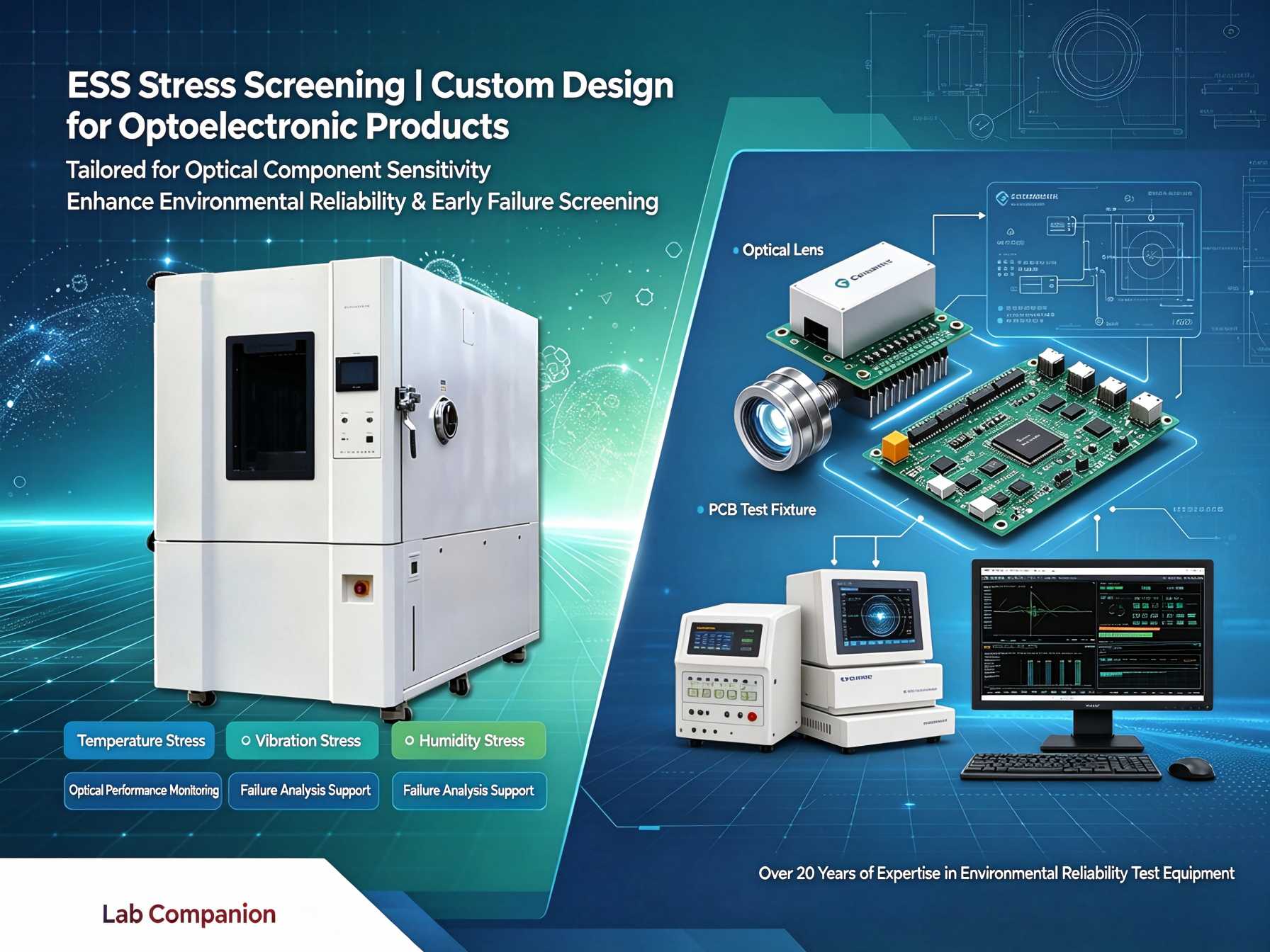
  • Lab Companion | ESS Stress Screening for Optoelectronic Products: Linear & High-Precision Temperature Ramp to Secure Optical Performance Lab Companion | ESS Stress Screening for Optoelectronic Products: Linear & High-Precision Temperature Ramp to Secure Optical Performance
    Oct 26, 2026
    Optoelectronic products such as optical modules and optical assemblies require both stable optical performance and electronic reliability. Their failures often manifest as optical performance degradation alongside structural defects. Environmental Stress Screening (ESS) before mass delivery is critical to weed out early failures and guarantee consistent optical performance. Given the high sensitivity of optical components to thermal disturbance, the ESS screening plan for optoelectronic products cannot be directly adopted from that for ordinary electronic devices. Rooted in the intelligent manufacturing base in Dongguan, Lab Companion has specialized in environmental reliability test equipment for over two decades. We provide tailored ESS stress screening solutions for the optical communication and optics industries. This article starts with failure mechanisms and outlines key considerations for ESS screening of optoelectronic products. 1. Typical Failure Mechanisms of Optoelectronic Products 1.1 Optical Performance Is Vulnerable to Thermal Stress The optical engine is highly sensitive to temperature changes. Thermal stress triggers wavelength shift and optical power fluctuation, directly degrading signal transmission quality. This is the core difference between optoelectronic devices and pure electronic components. 1.2 Thermal Fatigue of Interconnections and Packaging Lasers, photodetectors and high-speed circuits feature intricate interconnection structures. Under temperature cycling, mismatched Coefficients of Thermal Expansion (CTE) among different materials accumulate thermo-mechanical stress, which easily causes solder joint fatigue and package cracking. 1.3 Misalignment of Optical Paths and Microstructure Instability Optical assemblies rely on micron-level alignment precision. Deformation induced by temperature variation leads to optical misalignment and microstructure damage, which reduces optical indicators. Such damage is often latent and hard to detect in advance. 2. Core Requirements for ESS Screening of Optoelectronic Products 2.1 Linear and Controlled Temperature Ramp to Avoid Misjudgment of Optical Performance ESS for optoelectronics demands smooth temperature transition. Temperature overshoot and internal condensation must be prevented. Temperature overshoot instantly disturbs key indicators including optical power and wavelength; condensation corrodes optical end faces and circuits, introducing non-genuine failures and skewing screening results. Steady and linear temperature ramp is the foundation of optoelectronic ESS. 2.2 Compliance with Authorized Industry Specifications Reliability screening for optical communication components generally follows standards such as GR-468-CORE. Clear requirements are defined for temperature range, ramp rate, cycle count and dwell time. Equipment specifications must meet these standard requirements. 2.3 Adaptation to Mass Production Screening The optical communication industry features large shipment volumes. Production-line ESS needs simultaneous testing of multiple devices. The equipment shall support batch loading to match production tact time and improve screening coverage and efficiency. 3. Lab Companion ESS Stress Screening Solution for Optoelectronics 3.1 Wide Temperature Range with Multiple Linear Ramp Rates Standard models cover a temperature range from -70℃ to +150℃, with optional ramp rates of 5℃/min, 10℃/min and 15℃/min to suit different screening specifications for optical devices. 3.2 High-Precision Temperature Control and Uniform Thermal Field Temperature fluctuation ≤ ±0.3℃, temperature deviation ≤ ±2℃. Excellent internal thermal consistency ensures all samples in the same batch are exposed to identical thermal stress, delivering comparable and repeatable screening results. 3.3 Batch Loading & Full-Process Data Traceability Multi-layer sample racks are available for simultaneous testing of large batches of optoelectronic devices. The system automatically archives temperature profiles and test logs to satisfy quality control and traceability compliance requirements in the optical communication industry. 3.4 Flexible Customization Customizable chamber volume, temperature ramp rate, independent thermal zones and external data acquisition interfaces are available according to product dimensions and test conditions, catering to diverse test demands of optical modules and optical assemblies. 4. Equipment Selection Guide for Mass-Production ESS 4.1 Define Screening Parameters against Standards Determine the temperature range, ramp rate and cycle count based on specifications such as GR-468-CORE. Select equipment with adequate performance margin instead of operating continuously at full load. 4.2 Prioritize Linear Ramp and Anti-Condensation Performance Optoelectronic devices are sensitive to thermal shock. Focus on evaluating linear temperature ramp capability, anti-condensation design and thermal uniformity to avoid misjudgment caused by abnormal thermal disturbance. 4.3 Match Loading Configuration with Production Capacity For mass screening, prioritize models compatible with multi-layer racks and suitable chamber size to match production output and maximize sample quantity per test run. 4.4 Full-Cycle Technical Support Choose manufacturers with in-house manufacturing capacity and a sound service network. Reliable support covering installation, commissioning and calibration helps smooth the verification process for mass production of optoelectronic products. Conclusion The reliability of optoelectronic products stands for dual stability of optical performance and electronic structures. Based in Dongguan, Lab Companion delivers ESS stress screening solutions featuring wide temperature range, high-precision linear temperature ramp, stable thermal field, batch testing and full traceability, safeguarding the long-term stable operation of optical devices. Going forward, Lab Companion will keep focusing on environmental reliability test equipment and continuously empower reliability upgrading of the optical communication and optics industries.
    إقرأ المزيد
  • Lab Companion Rapid Temperature Change Test Chamber: Wide Temperature Range & High Precision for Stringent Thermal Cycling Reliability Testing Lab Companion Rapid Temperature Change Test Chamber: Wide Temperature Range & High Precision for Stringent Thermal Cycling Reliability Testing
    Oct 22, 2026
    Rapid Thermal Cycling: The Accelerator for Reliability Validation Reliability testing is no longer merely to verify whether a product “works”. Its core goal is to efficiently trigger and uncover latent defects. The rapid temperature change test chamber delivers controlled high temperature ramp rates to repeatedly apply thermal stress within a short cycle, cutting validation time and helping teams accelerate R&D iteration and production screening. As a national high-tech enterprise rooted in Dongguan, Lab Companion specializes in the R&D and manufacturing of environmental reliability test equipment. Serving the electronics manufacturing sector including semiconductors, automotive electronics and optical communications, our rapid temperature change chambers are engineered for demanding thermal cycling assessments. This article explains ramp rate specifications, failure acceleration mechanisms, key equipment features and selection guidelines. 1. Understanding Temperature Ramp Rate 1.1 What is Temperature Ramp Rate Temperature ramp rate refers to the speed of temperature rise or fall per unit time, measured in ℃/min. It is the core performance metric for rapid thermal cycling chambers. A higher ramp rate shortens each thermal cycle, allowing more cycles to be completed within the same test window and improving overall test throughput. 1.2 Multiple Ramp Rate Options Lab Companion rapid temperature change test chambers offer linear ramp rates of 5℃/min, 10℃/min and 15℃/min: 5℃/min: For standard thermal cycling qualification 10℃/min: Compliant with most industrial test specifications 15℃/min: Optimized for high-efficiency ESS (Environmental Stress Screening) 1.3 Controlled Linearity Matters More Than Raw Speed Faster does not always mean better. Non-linear temperature transitions easily lead to temperature overshoot and internal condensation, introducing artificial stress that may damage precision components and invalidate test results. A reliable rapid thermal cycling chamber must deliver both fast response and stable, linear temperature control. 2. How Rapid Thermal Cycling Accelerates Failure Detection 2.1 Thermal-Mechanical Stress to Expose Hidden Defects Electronic assemblies consist of multiple materials with different coefficients of thermal expansion (CTE). During rapid temperature swings, mismatched expansion and contraction generate concentrated thermal-mechanical stress at material interfaces. Higher ramp rates amplify this stress, revealing latent failures such as solder fatigue, package cracking and interface delamination at an earlier stage. 2.2 Shorter R&D Cycles for Faster Design Iteration Engineers often evaluate multiple design variants within tight schedules. High ramp rates reduce cycle duration, enabling the required number of thermal cycles to finish sooner. This speeds up design comparison, optimization and new product launch. 2.3 Efficient Production Screening for Quality Control In mass production screening, rapid thermal cycling cuts per-unit test time and increases factory throughput. The intensified thermal stress effectively weed out early failure units from batches, balancing screening effectiveness and production tact time. 3. Core Capabilities of Lab Companion Rapid Temperature Change Test Chamber 3.1 Wide Temperature Range with Margin for Severe Testing Standard models cover -70℃ to +150℃, covering mainstream thermal cycling requirements for semiconductors, automotive electronics and optical communications, with extra margin available for highly accelerated stress tests. 3.2 Multiple Linear Ramp Rates for Diverse Test Standards Selectable linear rates of 5 / 10 / 15℃/min support compliance with industry standards or internal stress screening, reconciling test validity and productivity. 3.3 High-Precision Temperature Control for Reproducible Results Temperature fluctuation ≤ ±0.3℃; temperature deviation ≤ ±2℃. Stable thermal field performance is maintained even under fast ramp conditions, ensuring comparable and repeatable test data across different batches and shifts. 3.4 Batch Testing & Data Traceability for Digital Quality Management Multi-layer racks support simultaneous testing of multiple samples to boost capacity. The system automatically logs temperature profiles and test records, satisfying digital quality control and traceability requirements. 4. Selection Guide for Rapid Temperature Change Test Chambers 4.1 Define Ramp Rate Based on Test Specifications First confirm the mandatory ramp rate stated in your test standard. For internal screening without fixed standards, higher ramp rates can be considered, with special attention to linear control performance. 4.2 Match Temperature Range and Accuracy Requirements The chamber working range must fully cover your test limits with sufficient margin. Precision specifications should guarantee consistent judgement. Lab Companion’s -70℃ ~ +150℃ range and tight control accuracy fit most common application scenarios. 4.3 Balance Throughput and Sample Protection While high ramp rates improve efficiency, excessive thermal stress may cause unintended damage to DUTs (devices under test). Select ramp rates and loading configurations according to material and structural characteristics. Custom solutions are available upon request. 4.4 Prioritize Long-Term Stability and Technical Support Rapid thermal cycling tests often run continuously for extended periods. Equipment reliability and vendor support directly affect R&D and production schedules. Choose a manufacturer with mature production capability and a comprehensive service network to secure stable operation over the full equipment lifecycle. Conclusion A rapid temperature change test chamber is a powerful tool that turns controlled thermal stress into actionable reliability insights. Equipped with wide temperature coverage, adjustable linear ramp rates, high-precision control, batch testing and data traceability, Lab Companion rapid thermal cycling chambers help R&D and QA teams expose product weaknesses faster and streamline validation workflows. Moving forward, Lab Companion will keep focusing on environmental reliability testing, delivering robust equipment and professional service to help industries uphold strict quality standards.
    إقرأ المزيد
  • Lab Companion Temperature Cycling Chamber for Router Modules: Equipment Solution for Full-Link Temperature Cycling Validation of Network Devices
    Oct 17, 2026
    I. Why Router Modules Require Temperature Cycling Testing 1.1 Mechanism of Temperature Variation Impact on Signal Transmission Quality As the core unit for network data forwarding, router modules integrate switching chips, network processors, PHY chips, high-speed differential signal traces and various passive components. The core objective of temperature cycling testing for router modules is not merely verifying basic power-on functionality, but maintaining acceptable signal integrity throughout the test. High-speed differential links within router modules are highly sensitive to temperature fluctuations. During temperature cycling, thermal expansion and contraction of PCB substrates and chip packages cause minor shifts in trace impedance, degrading eye diagram performance and reducing timing margin. For Wi-Fi 6/7 wireless router modules, the gain of power amplifiers and noise figure of low-noise amplifiers in the RF front-end drift with temperature, directly resulting in fluctuating wireless throughput and elevated packet loss rate. Temperature cycling simulates operating conditions under alternating high and low temperatures to assess module performance stability and functional reliability. It effectively activates early defects introduced by soldering processes and component batch variations. 1.2 Standard Basis for Router Module Temperature Cycling Testing Temperature cycling tests on router modules comply with multiple leading international and Chinese standards, including GB/T 2423.22, IEC 60068-2-14, MIL-STD-810G and ETSI EN 300 019. These specifications define clear requirements for test conditions, procedures, duration and temperature ramp rates. Certain router product certifications mandate environmental adaptability tests under temperature cycling conditions of -40°C to +85°C with 95%RH non-condensing humidity. During testing, samples must remain powered on while key metrics such as throughput, packet loss rate and signal strength are monitored in real time to verify communication stability under changing thermal conditions. 1.3 In-line Monitoring: Core Requirement for Router Temperature Cycling Testing Temperature cycling for router modules differs fundamentally from discrete component testing. Component testing only evaluates parameter recovery after thermal exposure. As fully functional network units, router modules must sustain continuous traffic forwarding throughout the thermal cycle. Even if functionality recovers once temperature returns to normal, any mid-test throughput drop, rising packet loss or temporary disconnection indicates temperature-related latent failure risks. Therefore, temperature cycling chambers for router modules must feature in-line monitoring ports to keep samples powered inside the chamber and capture real-time throughput, bit error rate and other performance data via external test instruments. II. Key Technical Requirements for Router Module Temperature Cycling Chambers 2.1 Superior Temperature Uniformity to Ensure Consistency in Multi-Module Testing Router modules are frequently tested in batches with multiple samples loaded simultaneously. Significant temperature variance across the chamber cavity would expose samples to inconsistent thermal stress and invalidate result comparability. Lab Companion adopts dual air duct circulation and multi-point sensor layout. Under full-load operation, temperature uniformity is controlled within ≤±2.0°C, temperature fluctuation ≤±0.5°C with temperature deviation of ±2°C. This specification ensures uniform thermal stress applied to samples placed at different positions in one batch, delivering comparable and repeatable data for batch screening and sampling inspection. 2.2 Anti-Condensation Design & In-line Monitoring Cable Ports Router modules operate powered-on inside the chamber. Condensation may form on component pins and PCB surfaces during temperature recovery from low temperature, leading to short circuits of test cables and distorted measurement readings. Lab Companion, a China-based manufacturer, implements systematic anti-condensation solutions covering airflow organization, humidity regulation and chamber structural design. The viewing window uses hollow coated electrically heated glass to prevent condensation at low temperatures. Dedicated electrical cable feedthrough ports are reserved on the chamber to route test cables outside, supporting continuous powered operation and real-time performance monitoring of samples. 2.3 Stable Temperature Control for Signal Integrity under Cycling Conditions Router modules are sensitive to ambient temperature disturbances. Throughput may degrade even when port indicators remain normal. The chamber shall provide stable temperature plateaus to minimize extra test errors introduced by control fluctuations. Lab Companion uses balanced PID temperature regulation combined with fuzzy logic control algorithms to sustain stable thermal conditions during long-duration continuous cycling tests. III. Complete Temperature Cycling Solution from Lab Companion (China) 3.1 Brand Background & Manufacturing Bases Founded in 2005 and headquartered in Dongguan, Guangdong, China, Lab Companion is a Chinese National High-Tech Enterprise and Guangdong Provincial Specialized, Refined, Differential & Innovative Enterprise. With over 20 years of expertise in environmental reliability test equipment, the company operates under ISO9001, ISO14001, ISO45001 and ISO27001 management systems, and its products carry EU CE certification. Lab Companion runs three R&D and manufacturing facilities across China: Dongguan, Kunshan and Chongqing. The Dongguan headquarters serves as the R&D hub and main production site for standard models, covering a plant area of 27,286 m² with an annual output of around 1,000 environmental test chambers. 3.2 Temperature Range & Ramp Rate Options Lab Companion TC series rapid temperature cycling chambers feature a standard temperature range of -70°C to +150°C, expandable up to +180°C. The range fully meets requirements from GB/T 2423.22, IEC 60068-2-14 and covers the typical industrial-grade test envelope of -40°C ~ +85°C for router modules. Five ramp rate options are available: 5°C/min, 10°C/min, 15°C/min, 20°C/min and 25°C/min. Both linear and non-linear temperature profiles are supported to match ramp requirements from different certification standards. 3.3 In-line Monitoring Ports & Powered Test Configuration For powered temperature cycling of router modules, dedicated electrical feedthrough ports can be configured. Modules inside the chamber connect to external traffic testers and maintain packet forwarding during cycling. Throughput, packet loss rate and signal strength are captured in real time. Multi-channel temperature acquisition can be extended to synchronously monitor the temperature of core chips on modules. 3.4 Multiple Chamber Volumes & Customization Capability TC series chambers are offered in standard volumes: 34L, 64L, 100L, 180L, 340L, 600L and 1000L. Models of 80L, 150L, 225L, 408L and 800L are in stock. Custom sizes ranging from 80L up to 8000L are available. For batch testing of small-to-medium router modules, chamber size can be selected according to sample loading quantity. In-line performance monitoring projects can be equipped with cable feedthrough and anti-condensation packages upon request. 3.5 Intelligent Control System & Full Data Logging Equipped with self-developed C100 PID temperature & humidity controller integrated with fuzzy logic algorithm and a color touchscreen, the system supports multi-segment programming, automatic data logging and report generation. Temperature profiles, actual ramp rates, dwell durations and alarm logs are recorded in standardized format and exportable after tests, supporting report compilation and batch traceability. Built-in multi-layer safety protections including over-temperature protection, compressor overload protection and fan fault alarm ensure stable operation for long unattended thermal cycling runs. IV. Typical Application Scenarios Throughput Validation for Wi-Fi Routers RF component gain and noise figure drift under temperature variation for Wi-Fi 6/7 devices and cause wireless throughput fluctuation. The TC series performs temperature cycling in accordance with IEC 60068-2-14 and GB/T 2423.22. Samples stay powered on while external testers continuously record throughput to verify wireless performance stability under thermal cycling. Packet Loss Testing for Enterprise Routers Packet loss rate is a key reliability metric for enterprise routers. TC series chambers reserve cable feedthrough ports to connect in-chamber modules to external traffic testers for real-time monitoring of packet loss and transmission latency. Extended multi-channel temperature sensing supports parallel testing of multiple router units. Temperature Cycling Stress Screening for Switch Modules Switch modules share similar temperature cycling requirements with router modules. The excellent temperature uniformity of TC series ensures identical thermal stress applied on all samples, delivering repeatable results for batch screening. Reliability Validation for IoT Gateway Modules IoT gateways typically require wide operating temperature tolerance. With wide temperature range and controllable linear ramp capability, TC series reproduces thermal stress to evaluate temperature adaptability of gateway modules. V. Equipment Selection Guidelines 5.1 Temperature Uniformity for Multi-Station Parallel Testing For multi-sample concurrent testing, prioritize full-load temperature uniformity. TC series achieves ≤±2.0°C uniformity under full load to guarantee consistent stress exposure. Evaluate cavity temperature field distribution based on sample quantity and layout during selection. 5.2 In-line Monitoring Ports and Anti-Condensation Design Router temperature cycling usually requires powered operation. Confirm anti-condensation solutions and cable feedthrough availability during selection to avoid condensation-induced short circuits during low-temperature recovery. If real-time throughput and packet loss monitoring are required, define interface types and data formats of external instruments at procurement stage. 5.3 Chamber Volume and Fixture Compatibility Calculate required cavity volume based on module dimensions and batch loading quantity. Reserve extra space for cable routing for powered tests. For multi-layer rack testing of multiple units, check rack load capacity and ensure airflow is not blocked. 5.4 Standard Compliance and Test Data Traceability TC series chambers comply with IEC 60068-2-14, GB/T 2423.22 and other mainstream test standards. For certification projects, built-in data logging fully retains thermal profiles to support audit and traceability. VI. Conclusion The core challenges of temperature cycling testing for router modules lie in preserving signal integrity under powered operation, uniform thermal field control across multi-station setups, and stable performance during long continuous cycling. Manufactured by Lab Companion from China, the TC series rapid temperature cycling chambers deliver a -70°C ~ +150°C wide temperature envelope, 5~25°C/min adjustable ramp rates, ≤±0.5°C temperature fluctuation and ≤±2.0°C full-load uniformity. Combined with systematic anti-condensation solutions, in-line cable feedthrough ports and self-developed C100 control system, the chambers provide full-link reliability temperature cycling validation for Wi-Fi routers, enterprise routers, switch modules and IoT gateway modules. Technical specifications and custom configurations can be further discussed according to project test requirements.
    إقرأ المزيد

  • Lab Companion Temperature Cycling Test Chamber for Electronic Components: Selection Guide Focusing on Temperature Uniformity and Anti‑Condensation Design Lab Companion Temperature Cycling Test Chamber for Electronic Components: Selection Guide Focusing on Temperature Uniformity and Anti‑Condensation Design
    Oct 14, 2026
    1. Core Requirements for Temperature Cycling Test of Electronic Components 1.1 Necessity of Component‑Level Reliability Verification Electronic components including capacitors, resistors, connectors, sensors and integrated circuits serve as fundamental building blocks for all electronic devices. During service, these components are subjected to temperature variations. Divergent coefficients of thermal expansion among different materials generate cyclic thermal stress at solder joint interfaces, inside packages and material bonding interfaces under repeated temperature cycling. Long‑term stress may cause solder joint fatigue, package cracking and bond‑wire breakage. Such failures cannot be detected under ambient‑temperature tests and will only emerge under cyclic alternating thermal stress. As a fundamental reliability validation method, temperature cycling test simulates temperature fluctuations during assembly, soldering and field operation, so as to evaluate mechanical and electrical integrity of components under alternating thermal stress. Specified by JEDEC JESD22‑A104, the standard for semiconductor device temperature cycling test, typical test conditions cover the range from ‑65 °C to +150 °C, with dwell time of 10‑15 minutes, temperature transition rate ≥15 °C/min and up to 1000+ test cycles. 1.2 Special Requirements for Test Chambers for Component Testing Characterized by small dimensions, large test batch sizes and dense electrical interfaces, electronic components impose distinct requirements compared with complete‑unit or large‑assembly testing. Temperature Uniformity: Excessive temperature deviation inside the chamber creates inconsistent thermal stress across samples in one batch and increases dispersion of test results. Anti‑Condensation Performance: Condensation forming on component surfaces or pins during temperature ramp‑up from low temperature may lead to short‑circuits and deviation in electrical parameter measurement for powered‑on tests. On‑line Monitoring Compatibility: Dedicated cable ports shall be available to route test harnesses out of the chamber for powered‑on monitoring. Batch‑Loading Capability: Fixture loading efficiency and contact reliability directly determine overall test throughput. 2. Lab Companion Complete Solution for Electronic‑Component Temperature Cycling Test 2.1 Corporate Strength & Manufacturing System Lab Companion (Guangdong Hongzhan Technology Co., Ltd.), founded in 2005 in Dongguan, is a National High‑Tech Enterprise and Guangdong Specialized‑Refined‑Differential‑Innovative Enterprise with over 20‑year experience in environmental reliability test equipment. The company operates under ISO 9001, ISO 14001, ISO 45001 and ISO 27001 management systems, and its products hold CE certification for EU markets. Three manufacturing bases are located in Dongguan, Kunshan and Chongqing. The Dongguan headquarters functions as the R&D center and main production site for standard chambers, covering a plant area of 27 286 m² with an annual output of approximately 1 000 environmental test chambers. 2.2 Key Performance Specifications of Temperature Cycling Chambers Standard temperature range: ‑70 °C ~ +150 °C, expandable up to +180 °C, fully covering temperature requirements defined in JESD22‑A104 and other mainstream semiconductor temperature‑cycling standards. Available temperature ramp rates: 5 °C/min, 10 °C/min, 15 °C/min, 20 °C/min, 25 °C/min. Both linear and non‑linear temperature profiles are supported to meet ramp‑rate requirements of diverse test standards. Temperature fluctuation: ≤±0.5 °C; temperature deviation: ≤±2 °C. 2.3 Temperature Uniformity and Anti‑Condensation Design Adopting dual‑air‑duct circulation together with multi‑point temperature sensor layout, the chamber achieves temperature uniformity ≤±2 °C under full‑load condition and ≤±0.5 °C under steady‑state conditions. This minimizes thermal‑stress discrepancy among components at different positions and suppresses data dispersion for batch testing. The built‑in anti‑condensation system prevents dew formation on component pins and housings during low‑to‑high temperature ramp‑up, ensuring stable powered‑on on‑line testing. The observation window adopts multi‑layer conductive‑film tempered insulating glass with surrounding heating wires to eliminate frosting and fogging at low temperatures for clear visual sample inspection. 2.4 Chamber Volume, Fixture and System Compatibility Standard chamber volumes: 34 L, 64 L, 100 L, 180 L, 340 L, 600 L, 1000 L. Custom non‑standard volumes from 80 L to 8000 L are available. Models can be selected according to component package dimensions and batch sizes, with custom‑designed loading fixtures offered upon request. Extended multi‑channel temperature acquisition enables multi‑point chamber‑field monitoring. Dedicated cable ports are reserved for on‑line electrical‑parameter measurement. The chamber supports connection to host PCs and LIMS laboratory management systems for automatic recording and export of test curves and datasets. 3. Typical Application Scenarios Passive Components (Capacitors & Resistors) Focus validation on capacitance drift, resistance shift and solder‑joint reliability under temperature variation. Compact‑volume chambers suit high‑volume batch testing and comply with industry specifications for passive‑component temperature cycling. Connectors & Sensors Evaluate contact‑resistance variation, material aging and sensor output drift under thermal cycling. Multi‑channel temperature acquisition monitors real‑time thermal conditions around DUTs (Devices Under Test). Integrated Circuits & Semiconductor Devices Temperature range and ramp‑rate options satisfy JESD22‑A104 requirements covering consumer‑grade to automotive‑grade semiconductors, supporting continuous durability testing for up to thousands of cycles. PCB Assembly‑Level Validation Large‑volume chambers accommodate complete PCB assemblies. The programmable controller automatically executes multi‑segment complex temperature profiles for board‑level component reliability assessment. 4. Key Selection Guidelines 4.1 Match Temperature Ramp Rate with Applicable Test Standards Ramp‑rate requirements vary across component specifications. JESD22‑A104 specifies ≥15 °C/min for certain test conditions, while other industrial standards may require 5‑10 °C/min. Select ramp‑rate options strictly per applicable test specifications to avoid over‑specification or insufficient performance. 4.2 Temperature Uniformity for Batch Testing For large‑scale simultaneous testing, temperature uniformity is critical to test‑data credibility. Lab Companion chambers maintain ≤±2 °C uniformity under full‑load. For high‑precision applications, steady‑state performance can be further evaluated. 4.3 Pre‑define Fixture Requirements and Electrical Interfaces Powered‑on on‑line testing is common for electronic components. Define harness quantity and dimensions at the selection stage to confirm proper cable port sizing. Custom fixtures can be developed for specific component packages. 4.4 Balance Chamber Volume Between Throughput and Thermal‑Field Performance Determine required volume based on sample quantity per test run. Insufficient volume reduces throughput; excessively large volume increases difficulty in maintaining homogeneous thermal field. Standard‑volume models are preferred, and non‑custom solutions are applied for special test conditions. 5. Conclusion Three core indicators dominate electronic‑component temperature‑cycling testing: temperature‑field uniformity, anti‑condensation capability and batch‑sample loading performance. Lab Companion temperature cycling chambers deliver wide temperature range of ‑70 °C ~ +150 °C, multi‑step ramp rates from 5 °C/min to 25 °C/min and temperature fluctuation ≤±0.5 °C. Supported by dual‑air‑duct circulation and proven anti‑condensation technology, alongside flexible volume options ranging from 80 L to 8000 L and custom fixture services, our chambers provide complete reliability‑test solutions for semiconductors, passive components and PCB assemblies. Further technical proposals can be customized against your exact test conditions.
    إقرأ المزيد
1 2 3 4 5 6 7 8 9
ما مجموعه 9الصفحات

اترك رسالة

اترك رسالة
إذا كنت مهتما بمنتجاتنا وتريد معرفة المزيد من التفاصيل ، فالرجاء ترك رسالة هنا ، وسوف نقوم بالرد عليك في أقرب وقت ممكن.
إرسال

وطن

منتجات

واتس اب

اتصل بنا